Bang & Olufsen
B&O Beogram CD 5500 6500 7000 COMPLETE electrolytic capacitor set recap repair
B&O Beogram CD 5500 6500 7000 COMPLETE electrolytic capacitor set recap repair
Kan beschikbaarheid voor afhalen niet laden
Complete electrolytic capacitor set for all boards of the Bang and Olufsen Beogram CD 5500, CD6500 and CD7000
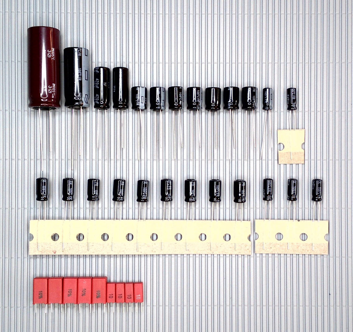
We now offer you the complete set, consisting of a total of 34 capacitors, which in the vast majority of cases have higher temperature and voltage ratings (see the description below this offer):
Panasonic-WIMA quality:
This set consists of 24 Panasonic FR-A capacitors, known for their audio quality and enormous service life, five WIMA MKS film capacitors for values below 4.7µF (as FR-A capacitors are not available for these values), also with excellent audio quality and an almost unlimited service life, and a long-lasting filter capacitor for the power supply.
Since the WIMA MKS film capacitor with a value of 3.3µF is no longer produced, we had to find an adequate replacement. We found it in the Panasonic EB-A electrolytic capacitor, which meets our expectations in terms of service life and suitability for audio devices (most capacitors suitable for audio have a highly unsatisfactory service life). However, this only applies to the one value, 3.3µF, for which four Replacement capacitors are supplied. The photo still shows the capacitors that are no longer available, until the photo is replaced by a new one.
We offer a 60-day right of withdrawal (for unused electrolytic capacitors)
General procedure for replacing capacitors
General procedure for replacing capacitors (see at the very bottom)
First of all, it is advisable to take lots of photos: of the wiring, the
circuit board, and the capacitors.
Electrolytic capacitors must be installed with the correct polarity; the
negative pole is usually marked by a strip on the side of the housing.
It is helpful if you can see which way the capacitor was installed—the one
you are holding between your fingers—so that you can install the new one the
right way around (in some cases, you cannot trust printed circuit boards, if they
exist).
In individual cases, we recommend desoldering with desoldering braid and a
desoldering pump. An electronic desoldering station with a heated suction gun would be best, but it is usually not worth purchasing for smaller
projects.
First, get an idea of the situation. Keep in mind that in the vast majority of
cases, electrolytic capacitors were supplied with a higher voltage rating.
The maximum permissible voltage (V) may be the same as that of the
old capacitor, but may very well be higher and must never be lower.
Voltage Capability
In 1987, Due to Europe-wide harmonization, the mains
voltage in some countries was increased from 220V (198V-242V was possible)
to 230V (207V-253V has been possible since then).
This may only concern Europe, but a similar situation is possible in countries with a 100-127V
mains voltage, with the same effect.
Due to the smoothening of the DC by electrolytic capacitors, which usually takes place immediately after the transformer and rectification, and with the DC voltage regulation only taking place afterwards, many such capacitors are now operated above the permissible voltage. The voltage capability was usually calculated very tightly due to the bigger size and higher price of caps with an increased one. This is particularly noticeable in Philips CD players, where the 16V caps in the power supply now run at 16V or above.
It is therefore strongly recommended that devices that can be switched from 220 to 240V (or from 100/110/120 one step increasing) be switched or soldered accordingly if you live in an area such a voltage increasement has taken place. Unfortunately, some do not offer this option; safety is then installed with an increased voltage resistance of the electrolytic capacitors.
Capacitors have become smaller over time, so that size is no longer an exclusion criterion for voltage capability.
An example of this:
There are four different types of 47µF capacitors installed in your device:
47µF/10V,
47µF/25V,
47µF/35V and
47µF/50V.
We would supply you with the following replacement types:
2x 47µF/35V as replacement for 10V and 25V
2x 47µF/63V as replacement for 35V and 50V
Although the original comes with a 35V capacitor, a 63V capacitor is supplied to increase the voltage resistance.
Temperature resistance
In the past, only capacitors were installed that had a temperature resistance of 85°C, as this corresponded to the state of electrolytic capacitor production at the time.
Today these can easily be replaced by ones with a temperature resistance of 105°C; Unfortunately, some capacitors on the world market are sometimes only available in 85°C versions.
A set may therefore also contain some capacitors that only have a temperature rating of 85°C, although we try to avoid this.
General procedure for replacing capacitors
First, it is advisable to take plenty of photos: of the wiring, the circuit board, and the capacitors.
Electrolytic capacitors must be installed with the correct polarity; in your case, the negative terminal is generally marked by a stripe along the side of the housing.
It is helpful to be able to check how the capacitor you are currently holding between your fingers was installed, so that you can install the new one the right way around (in some cases, you cannot trust the markings on the circuit board either, if present).
For individual cases, we recommend desoldering with the help of desoldering braid and a desoldering pump. Ideally, you would use an electronic desoldering station with a heated suction gun, but purchasing one is usually not worthwhile for smaller projects.
First, assess the situation. Keep in mind that in the vast majority of cases, electrolytic capacitors with a higher voltage rating were supplied.
The value of the maximum permissible voltage (V) may match that of the old capacitor, but it may very well be higher and must never be lower.
Voltage rating
In 1987, this was harmonized in Europe, which meant that for some countries the voltage increased from 220V (198V-242V were possible) to approximately 230V (207V-253V have been possible since then).
In other countries with 100-130V mains voltage
Because filtering by electrolytic capacitors usually takes place immediately after the transformer and rectification, with voltage regulation occurring only afterward, many such capacitors are already operated above their permissible voltage, which was often calculated very narrowly due to physical size constraints (particularly noticeable in Philips CD players).
It is therefore strongly recommended that devices which can be switched from 220 to 240V be appropriately switched or rewired. Unfortunately, some do not offer this option; in such cases, safety is achieved by using electrolytic capacitors with a higher voltage rating.
Capacitors have become smaller over time, so physical size is no longer an exclusion criterion for a higher voltage rating.
An example:
Your device contains four different types of 47µF capacitors, each installed in four locations:
47µF/10V,
47µF/25V,
47µF/35V and
47µF/50V.
The replacement types would be supplied by us as follows:
2x 47µF/35V as replacements for 10V and 25V
2x 47µF/63V as replacements for 35V and 50V
Although the original includes a 35V capacitor, a 63V capacitor is supplied instead to provide a higher voltage rating.
Temperature rating
In the past, only capacitors rated for 85°C were installed, as this corresponded to the state of electrolytic capacitor manufacturing at the time.
Today, these can simply be replaced with ones rated for 105°C; unfortunately, however, individual capacitors on the global market are occasionally available only in an 85°C version.
A set may therefore also contain some capacitors rated for only 85°C, even though we try to avoid this.
General note: It is becoming increasingly difficult to source the small electrolytic capacitor values 0.1µF, 0.22µF, 0.33µF and 0.47µF from current production.
If your desired electrolytic capacitor set contains these values, the very suitable for hi-fi applications KEMET R82 series film capacitors will be included instead from now on. For the same reason, once stocks are depleted, the WIMA MKS film capacitors with values of 2.2µF and 3.3µF will be replaced by the excellent PANASONIC electrolytic capacitors from the EB-A series.
Brand: Bang & Olufsen
Model: Beogram CD5500 CD6500 CD7000
Country of origin: Germany
Christoph Mistler
An der Kull 51
DE-41844 Wegberg
Email: info@80s-hifi-classics.com
Product documents:
INSTALLATION_INSTRUCTIONS:
DE,EN,ES,FR,IT,NL,PL,PT.pdf
Hazard warnings
Hazard warnings
Information on product safety
- Please keep out of the reach of children!
- Contains small parts, risk of suffocation!
- Electrolytic capacitors may contain toxic electrolyte!
Risk of poisoning!
- Polarity must be observed!
- Work with the device unplugged and de-energized
- Capacitors may still store life-threatening voltages even after a long period of non-use!
Information on product safety
- Please keep out of the reach of children!
- Contains small parts, risk of suffocation!
- Electrolytic capacitors may contain toxic electrolyte!
Risk of poisoning!
- Polarity must be observed!
- Work with the device unplugged and de-energized
Information on product safety
- Please keep out of the reach of children!
- Contains small parts, risk of suffocation!
- Electrolytic capacitors may contain toxic electrolyte!
Risk of poisoning!
- Polarity must be observed!
- Work with the device unplugged and de-energized
- Capacitors may still store life-threatening voltages even after a long period of non-use!
Information on product safety
- Please keep out of the reach of children!
- Contains small parts, risk of suffocation!
- Electrolytic capacitors may contain toxic electrolyte!
Risk of poisoning!
- Polarity must be observed!
- Work with the device unplugged and de-energized
- Capacitors may still store life-threatening voltages even after a long period of non-use!
Information on product safety
- Keep out of reach of children!
- Contains small parts, risk of suffocation!
- Electrolytic capacitors may contain toxic
electrolyte! Risk of poisoning!
- Polarity must be observed!
- Work with the device disconnected from the power supply and de-energized
- Capacitors may still store life-threatening voltages
even after a long period of non-use!
Information on product safety
- Please keep out of the reach of children!
- Contains small parts, risk of suffocation!
- Electrolytic capacitors may contain toxic electrolyte!
Risk of poisoning!
- Polarity must be observed!
- Work with the device unplugged and de-energized
- Capacitors may still store potentially fatal voltages
even after a long period of non-use!
Information on product safety
- Keep out of reach of children!
- Contains small parts, risk of suffocation!
- Electrolytic capacitors may contain
toxic electrolyte! Risk of poisoning!
- Polarity must be observed!
- Work with the device unplugged and de-energized-
Capacitors may still store potentially fatal voltages
even after a long period of non-use.
Assembly instructions
Assembly instructions
Installation and assembly instructions
This type-specific capacitor set is intended to replace
the electrolytic capacitors present in the respective device; either because
because the existing capacitors are defective or because the ones we offer
better than the original ones (upgrade).
1. First of all, it is advisable to take lots of photos. Of
of the wiring, circuit board, and capacitors. It is helpful if you can
check how the capacitor you are currently holding between your fingers was installed
the wiring, circuit board, and capacitors. It is helpful if you can
between your fingers so that you can install the new one the right way round
(in some cases, the markings on the circuit board cannot be trusted, if present).
note that in the vast majority of cases the new electrolytic capacitors
were supplied with a higher voltage rating 1.
3. Proceed in order: desolder a defective electrolytic capacitor
desolder a defective electrolytic capacitor and solder in a new one.
1 The maximum permissible voltage (V) rating may match that of the
of the old capacitor
match the old capacitor, but it may certainly be higher and must never
never be lower.
An example:
Your device contains four different types of
47µF capacitors
installed:
47µF/10V, 47µF/25V,
47µF/35V and
47µF/50V.
As replacement types, we would supply the following
receive:
2x 47µF/35V as a replacement for 10V and 25V
2x 47µF/63V as a replacement for 35V and 50V
Although the original includes a 35V capacitor, a
so that
the voltage rating is higher, a 63V capacitor
supplied.
2 We recommend desoldering with the help of
desoldering braid and a manual desoldering pump. The best option would be
an electronic desoldering station with a heated suction gun, but purchasing one
is generally not worthwhile for smaller projects.
Installation and assembly instructions
This type-specific capacitor set is intended to replace the
electrolytic capacitors in the respective device; either because the existing
capacitors are defective or because the ones we offer are of better quality
than the original ones (upgrade).
1. First of all, it is advisable to take lots of photos. Of
the wiring, circuit board, and capacitors.
Electrolytic capacitors are generally polarized; they have a
positive and negative lead or side. It is helpful if you can look up which way
capacitor you are holding between your fingers was installed so that the new
it can be installed the right way round (in some cases, you cannot trust the
circuit board markings, if any).
2. Then, get an idea of the situation. Remember that in the
vast majority of cases, the new capacitors were supplied with a higher voltage rating
resistor (see note about the permitted voltage below).
3. Proceed in order: desolder an old capacitor, solder in a
new one (see note about desoldering tools below)
Permissible Voltage: The value of the maximum permissible
voltage (V) may match that of the old capacitor, but may be higher and may
NEVER be smaller, unless the device's service manual shows a lower voltage
at that point.
An example:
Your device has four different types of 47µF capacitors
installed:
47µF/10V, 47µF/25V,
47µF/35V and
47µF/50V.
We would supply you with the following replacement types:
2x 47µF/35V as a replacement for 10V and 25V
2x 47µF/63V as a replacement for 35V and 50V
Although the original comes with a 35V capacitor and we
could supply a 35V, a 63V capacitor is supplied to increase the voltage
resistance.
Desoldering tools: In individual cases, we recommend
desoldering using desoldering braid and a manual desoldering suction pump.
best option would be an electronic desoldering station with a heated suction
gun, but this is usually not worth buying for smaller projects.
Assembly and installation instructions
This type-specific capacitor kit is intended to
replace the electrolytic capacitors in the device concerned; either because
that the existing capacitors are defective, either because the ones we
we offer are of higher quality than the originals (upgrade).
1. First, it is advisable to take plenty of
photos. The wiring, circuit board, and capacitors.
Electrolytic capacitors are generally
polarized, they have a positive and negative lead or side. It is a good idea to
be able to check which way the capacitor you are holding between your fingers
was installed so that the new one can be installed in the correct orientation (so that
in some cases, you cannot rely on the markings on the circuit
printed on it, if any).
2. Next, assess the situation. Remember
noting that in the vast majority of cases, the new capacitors have been
supplied with a higher voltage rating (see the note on voltage
permissible voltage below).
3. Proceed in order: desolder an old capacitor,
solder a new one (see the note on desoldering tools below)
Permissible voltage: The maximum permissible voltage
permissible (V) may match that of the old capacitor, but may
be higher and can NEVER be lower, unless
the device's service manual indicates a lower voltage at this point.
An example:
Your device is equipped with four different types of
47µF capacitors installed:
47µF/10 V, 47µF/25 V,
47µF/35 V and
47µF/50 V.
We offer you the following replacement types:
2x 47µF/35V as a replacement for 10V and 25V
2x 47µF/63V as a replacement for 35V and 50V
Although the original comes with a 35V capacitor
and so that we can supply a 35V, a 63V capacitor is supplied to
increase the voltage rating.
Desoldering tools: in some cases, we recommend
to desolder using desoldering braid and a suction pump
manual desoldering iron. The best option would be a desoldering station
electronics with a heated suction gun, but it isn't worth
generally isn't worth buying it for smaller projects.
Installation and assembly instructions
This type-specific capacitor set is intended
to replace the electrolytic capacitors in the respective device; both because
the existing capacitors are defective, and because those we offer are of
better quality than the original ones (upgrade).
1. First of all, it is advisable to take many photos. Of the
wiring, circuit board, and capacitors.
Electrolytic capacitors are generally polarized,
have one positive and one negative lead or side. It is helpful if you can
check how the capacitor you are holding was installed
finger so that the new one can be installed correctly (in
in some cases you cannot rely on the circuit board markings, if there are
they are).
2. Then, get an overview of the situation. Remember that in
in the vast majority of cases, the new capacitors have been supplied with
a higher voltage rating (see the note on permissible voltage
below). 3. Proceed in order: desolder an old capacitor,
solder a new one (see the note on desoldering tools
below)
Permissible voltage: the maximum voltage rating
permissible voltage (V) may match that of the old capacitor, but it may
be higher and can NEVER be lower, unless the device's service manual
device's service manual does not specify a lower voltage at that point.
An example: The device has four different types of
47µF capacitors installed:
47µF/10V, 47µF/25V,
47µF/35V and
47µF/50V.
We will provide you with the
following replacement types:
2x 47µF/35V as a replacement for 10V and 25V
2x 47µF/63V as a replacement for 35V and 50V
Although the original is equipped with a 35V capacitor and
we could supply one rated at 35V, a 63V capacitor is supplied
increase the voltage rating.
Desoldering tools: in individual cases, we recommend
to desolder using desoldering braid and a suction pump
manual desoldering iron. The best option would be a desoldering station
electronics with a heated suction gun, but it usually isn't worth the
worth buying it for smaller projects.
Installation and assembly instructions
This type-specific capacitor set is intended to
to replace the electrolytic capacitors in the respective device; or
because the existing capacitors are faulty, either because the capacitors that
that the ones we offer are of better quality than the originals (upgrade).
1. First of all, it is advisable to take many photographs. Of
the wiring, the printed circuit board, and the capacitors.
Electrolytic capacitors are usually polarized; they
have a positive and negative lead or side. It is a good idea to check
which way the capacitor you are holding between your fingers was installed,
so that you can install the new one correctly (in some cases
you cannot rely on the markings on the printed circuit boards, if any).
2. Then assess the situation. Do not forget
that in the vast majority of cases the new capacitors were
supplied with a higher voltage rating (see the note on permitted
voltage below).
3. Proceed in the correct order: desolder an old
capacitor, solder in a new one (see the note about tools for
desolder below)
Permitted voltage: The value of the maximum permitted
voltage (V) may match that of the old capacitor, but may be higher
and must NEVER be lower, unless the device's service manual
that point indicates a lower voltage.
An example:
Your device has four different types
47µF capacitors installed:
47µF/10V, 47µF/25V,
47µF/35V and
47µF/50V.
We supply you with the following replacement types:
2x 47µF/35V as a replacement for 10V and 25V
2x 47µF/63V as a replacement for 35V and 50V
Although the original comes with a 35V capacitor
and when we can supply you with a 35V one again, a 63V capacitor is included to
to increase the voltage rating.
Desoldering tool: In individual cases
we recommend desoldering using desoldering braid and a manual
desoldering pump. The best option would be an electronic desoldering station with a
There may be a heated desoldering gun, but this is usually too expensive to buy for
smaller projects.
Installation and assembly instructions
This type-specific capacitor set is
intended for replacing the electrolytic capacitors in a given device;
either because the existing capacitors are faulty or because the ones offered
we supply are of better quality than the originals (upgrade).
1. First of all, it is advisable to take many photos.
Wiring, printed circuit board, capacitors.
Electrolytic capacitors are generally polarized,
have a positive and negative lead or side. It is a good idea to check which way
the capacitor that you are holding between your fingers was installed so that the new one could
be installed correctly (in some cases, you cannot rely on
printed circuit board, if any).
2. Then, assess the situation. Remember that in
in the vast majority of cases, the new capacitors were supplied with
higher voltage rating (see note on permitted voltage
below).
3. Proceed in order: desolder the old capacitor, solder in
a new one (see note on desoldering tools below)
Permitted voltage: The maximum permitted voltage rating
voltage (V) may match the voltage of the old capacitor, but may be higher
and can NEVER be lower, unless the device's service manual
indicates a lower voltage at this point.
Example:
Four different types of capacitors are installed in the device
47µF:
47µF/10V, 47µF/25V,
47µF/35V and
47µF/50V.
We will provide you with the following replacement types:
2x 47µF/35V as a replacement for 10V and 25V
2x 47µF/63V as a replacement for 35V and 50V
Although the original is fitted with a 35V capacitor, and we
we can supply 35V, a 63V capacitor is supplied to increase the
voltage rating.
Desoldering tools: In individual cases
we recommend desoldering with desoldering braid and a manual suction pump for
desoldering. The best option would be an electronic desoldering station
with a heated suction gun, but it is usually not worth buying one for smaller
projects.
Installation and assembly instructions
This specific set of capacitors is intended
to replace the electrolytic capacitors in the respective device; whether
because the existing capacitors are faulty or because the ones we offer
are of better quality than the originals (upgrade).
1. First of all, it is advisable to take many
photographs. Of the wiring, the circuit board, and the capacitors.
Electrolytic capacitors are mostly
polarized; they have a positive and negative lead or side. It is helpful if you can
check how the capacitor you are holding between your fingers was
installed so that the new one can be installed correctly (in some
cases you cannot rely on the circuit board markings, if any).
2. Then, assess the situation. Remember that in
in the vast majority of cases, the new capacitors were supplied with a
higher voltage rating (see note on permitted voltage below).
3. Proceed in order: desolder an old capacitor,
solder in a new one (see note on desoldering tools below)
Permitted voltage: The maximum permitted voltage rating (V)
may match that of the old capacitor, but may be higher and NEVER
lower, unless the device's service manual indicates a voltage
lower at this point.
An example:
Your device has four different types of
47µF capacitors installed:
47µF/10V, 47µF/25V,
47µF/35V and
47µF/50V.
We will provide the following replacement types:
2x 47µF/35V as a replacement for 10V and 25V
2x 47µF/63V as a replacement for 35V and 50V
Although the original comes with a 35 V capacitor and
we can supply a 35 V one, a 63 V capacitor is supplied to increase the
voltage rating.
Desoldering tools: In individual cases,
we recommend desoldering using desoldering braid and a suction pump
manual desoldering suction tool. The best option would be a desoldering station
electronics with a heated suction gun, but it is generally not worth it
buy for smaller projects.
Installation and assembly instructions
This type-specific capacitor kit is
designed to replace the device's electrolytic capacitors
either because the existing capacitors are defective or
because the ones we offer are of better quality than the originals
(update).
1. First of all, it is advisable to take plenty of
photographs. Of the wiring, the circuit board, and the capacitors.
Electrolytic capacitors are mostly
polarized, they have a positive side and a negative side. It is good that you can
check which direction the capacitor you are holding was installed in
so that you can install the new one in the correct orientation (in some cases you cannot
you can rely on the circuit board markings, if any).
2. Next, get an idea of the situation. Remember
since in the vast majority of cases the new capacitors were supplied with
a higher voltage rating (see the note on the permitted voltage below)
continuation).
3. Proceed in order: desolder one old capacitor, solder
a new one (see the note about desoldering tools below)
continuation)
Voltage rating: the maximum permitted voltage value (V)
may match that of the old capacitor, but it may be higher and NEVER
lower, unless the device's service manual specifies a lower voltage
lower at that point.
An example:
Your device has four different types of
47 µF capacitors:
47 µF/10 V, 47 µF/25 V,
47 µF/35 V and
47 µF/50 V.
We will supply you with the following replacement types:
2x 47µF/35V as a replacement for 10V and 25V
2x 47µF/63V as a replacement for 35V and 50V
Although the original comes with a 35V capacitor and
we could supply a 35V one, a 63V capacitor is supplied to
increase the voltage rating.
Desoldering tools: In individual cases,
we recommend desoldering using desoldering braid and a suction pump
manual desoldering tool. The best option would be a desoldering station
electronics with a heated suction gun, but it is generally not worth it
worth buying it for smaller projects.
Manufacturer
Manufacturer
Bang & Olufsen
Share