Bang & Olufsen
B&O Beogram CD 5500 6500 7000 Electrolytic Capacitor Set COMPLETE recap repair
B&O Beogram CD 5500 6500 7000 Electrolytic Capacitor Set COMPLETE recap repair
Couldn't load pickup availability
Complete electrolytic capacitor set for all
boards of the Bang & Olufsen Beogram CD5500, CD6500 and CD7000 CD player
(Deutsch siehe einige Zeilen darunter)
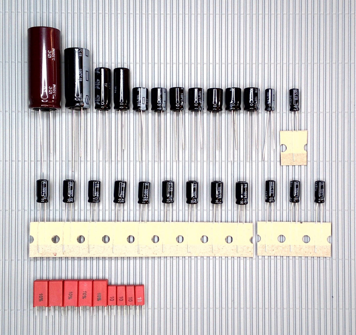
We offer you a complete set for this player, consisting of a total of 34 capacitors. In most cases, the electrolytic capacitors
have a higher temperature and voltage resistance (see the description under
this offer):
Panasonic-WIMA-Quality:
This set consists of 24 Panasonic FR-A capacitors, famous for their audio quality and enormous life, nine WIMA MKS foil capacitors for the values below 4.7µF, also of excellent audio quality and nearly unlimited life and one long life filter capacitor for the power supply.
We offer 60 days unused return
Complete electrolytic capacitor set for all boards of the Bang & Olufsen Beogram CD 5500, CD6500 and CD7000
We now offer you the complete set, consisting of a total of 34 capacitors, which in most cases have higher temperature and voltage resistance (see the description below this offer):
Panasonic-WIMA quality:
This set consists of 24 Panasonic FR-A capacitors, known for their audio quality and enormous lifespan, nine WIMA MKS film capacitors for values below 4.7µF (as not available as FR-A), also with excellent audio quality and almost unlimited lifespan, and a long-lasting filter capacitor for the power supply.
We offer a right of withdrawal of 60 days (unused electrolytic capacitors)
General procedure for replacing capacitors
General procedure for replacing capacitors (see below)
First of all, it is advisable to take lots of photos. From the wiring, from the
circuit board, from the capacitors.
Electrolytic capacitors must be installed with the correct polarity; the
negative pole is usually marked by a strip on the side of the housing.
It's good if you can see which way around the capacitor was installed, which
you're holding between your fingers so that you can install the new one the
right way round (in some cases you can't trust printed circuit boards, if they
exist).
In individual cases, we recommend desoldering using desoldering wire and a
desoldering suction pump. An electronic desoldering station with a heated
suction gun would be best, but it is usually not worth purchasing for smaller
projects.
First get an idea of the situation. Keep in mind that in the vast majority of
cases, electrolytic capacitors were supplied with a higher voltage rating.
The value of the maximum permissible voltage (V) may be the same as that of the
old capacitor, but may very well be higher and may never be smaller.
Voltage Capability
In 1987, due to Europe-wide harmonization, the mains
voltage in some countries has been increased from 220V (198V-242V was possible)
to 230V (207V-253V is possible since then).
This may only concern Europe, but similar is possible in countries with a 100-127V
mains voltage with the same effect.
Due to the smoothening of the DC by electrolytic capacitors, which usually
takes place immediately after the transformer and rectification, and with the DC
voltage regulation only taking place afterwards, many such capacitors are now
operated above the permissible voltage. The voltage capability was usually calculated
very tightly due to the bigger size and higher price of caps with an increased
one. This is particularly noticeable in Philips CD players, where the 16V caps
in the power supply now run at 16V or above.
It is therefore strongly recommended that devices that can be switched from 220
to 240V (or from 100/110/120 one step increasing) be switched or soldered
accordingly if you live in an area such a voltage increasement has taken place.
Unfortunately, some do not offer this option; safety is then installed with an
increased voltage resistance of the electrolytic capacitors.
Capacitors have become smaller over time, so that size is no longer an
exclusion criterion for voltage capability.
An example of this:
There are four different types of 47µF capacitors installed in your device:
47µF/10V,
47µF/25V,
47µF/35V and
47µF/50V.
We would supply you with the following replacement types:
2x 47µF/35V as replacement for 10V and 25V
2x 47µF/63V as replacement for 35V and 50V
Although the original comes with a 35V capacitor, a 63V capacitor is supplied
to increase the voltage resistance.
Temperature resistance
In the past, only capacitors were installed that had a temperature resistance
of 85°C, as this corresponded to the state of electrolytic capacitor production
at the time.
Today these can easily be replaced by ones with a temperature resistance of
105°C; Unfortunately, some capacitors on the world market are sometimes only
available in 85°C versions.
A set may therefore also contain some capacitors that only have a temperature
rating of 85°C, although we try to avoid this.
General procedure for replacing capacitors
First of all, it is advisable to take lots of photos. From the wiring, from the
circuit board, from the capacitors.
Electrolytic capacitors must be installed with the correct polarity; the
negative pole is usually marked by a strip on the side of the housing.
It's good if you can see which way around the capacitor was installed, which
you're holding between your fingers so that you can install the new one the
right way round (in some cases you can't trust printed circuit boards, if they
exist).
In individual cases, we recommend desoldering with
the help of desoldering wick and a desoldering suction pump. An electronic desoldering
station with a heated suction gun would be best, but its purchase is usually
not worthwhile for smaller projects.
First, get an idea of the situation. Keep in mind that in most cases, electrolytic
capacitors with higher voltage ratings were supplied.
The value of the maximum permissible voltage (V) may match that of the old
capacitor, but it may very well be higher and must never be smaller.
Voltage Resistance
In 1987, due to harmonization across Europe, this meant an increase in mains
voltage for some countries from 220V (198V-242V was possible) to approx. 230V
(207V-253V has been possible since then).
In other countries with 100-130V mains voltage
Due to the filtering by electrolytic capacitors, which usually takes place immediately
after the transformer and rectification, and the voltage regulation only
occurring afterwards, many such capacitors are now operated above the
permissible voltage, which was usually calculated very tightly due to the size
(especially noticeable in Philips CD players).
Therefore, it is strongly recommended that devices that can be switched from
220 to 240V be switched or soldered accordingly. Unfortunately, some do not
offer this option; in this case, safety is built in with an increased voltage
resistance of the electrolytic capacitors.
Capacitors have become smaller over time, so that size is no longer an
exclusion criterion for higher voltage resistance.
An example of this:
Your device contains four different types of 47µF capacitors:
47µF/10V,
47µF/25V,
47µF/35V and
47µF/50V.
You would receive the following replacement types from us:
2x 47µF/35V as replacement for 10V and 25V
2x 47µF/63V as replacement for 35V and 50V
Although the original includes a 35V capacitor, a 63V capacitor is supplied to
increase the voltage resistance.
Temperature Resistance
In the past, only capacitors with a temperature resistance of 85°C were
installed, as this corresponded to the state of electrolytic capacitor
production at the time.
Today, these can easily be replaced by ones with a temperature resistance of
105°C; unfortunately, some capacitors on the world market are sometimes only
available in 85°C versions.
A set may therefore also contain some capacitors that only have a temperature
resistance of 85°C, even if we try to avoid this.
Christoph Mistler
An der Kull 51
DE-41844 Wegberg
Email: info@80s-hifi-classics.com
Hazard statements
Hazard statements
Informationen zur Produktsicherheit
- Bitte außerhalb der Reichweite von Kindern aufbewahren!
- Enthält Kleinteile, Erstickungsgefahr!
- Elkos enthalten möglicherweise giftiges Elektrolyt!
Vergiftungsgefahr!
- Polung muss beachtet werden!
- bei ausgestecktem Gerät und Spannungsfrei arbeiten
- Kondensatoren können auch nach längerem Nicht-Betrieb noch
lebensgefährliche Spannungen gespeichert haben!
Information on product safety
- Please keep out of the reach of children!
- Contains small parts, risk of suffocation!
- Electrolytic capacitors may contain toxic electrolyte!
Risk of poisoning!
- Polarity must be observed!
- Work with the device unplugged and de-energized
- Capacitors may still store life-threatening voltages even after a long period of disuse!
Informations sur la sécurité des produits
- Veuillez tenir hors de portée des enfants !
- Contient de petites pièces, risque d'étouffement !
- Les condensateurs électrolytiques peuvent contenir un
électrolyte toxique ! Risque d'intoxication !
- La polarité doit être respectée !
- Travaillez avec l'appareil débranché et hors tension
- Les condensateurs peuvent encore accumuler des tensions
dangereuses même après une longue période de non-utilisation !
Informazioni sulla sicurezza del prodotto
- Tenere fuori dalla portata dei bambini!
- Contiene piccole parti, rischio di soffocamento!
- I condensatori elettrolitici possono contenere elettrolita
tossico! Rischio di avvelenamento!
- È necessario rispettare la polarità!
- Lavorare con il dispositivo scollegato e senza corrente
- I condensatori possono ancora accumulare tensioni pericolose per la vita anche dopo un lungo periodo di inattività!
Informatie over productveiligheid
- Buiten bereik van kinderen houden!
- Bevat kleine onderdelen, verstikkingsgevaar!
- Elektrolytische condensatoren kunnen giftige elektrolyt
bevatten! Vergiftigingsgevaar!
- Polariteit moet in acht worden genomen!
- Werk met het apparaat losgekoppeld en spanningsloos
- Condensatoren kunnen nog steeds levensbedreigende
spanningen opslaan, zelfs na een lange periode van inactiviteit!
Informacje na temat bezpieczeństwa produktu
- Przechowywać w miejscu niedostępnym dla dzieci!
- Zawiera małe części, ryzyko uduszenia!
- Kondensatory elektrolityczne mogą zawierać toksyczny
elektrolit! Ryzyko zatrucia!
- Należy przestrzegać biegunowości!
- Pracuj z urządzeniem odłączonym od zasilania i pozbawionym
zasilania
- Kondensatory mogą nadal gromadzić napięcia zagrażające
życiu nawet po długim okresie nieużywania!
Informações sobre a segurança do produto
- Por favor, mantenha fora do alcance das crianças!
- Contém peças pequenas, risco de asfixia!
- Os condensadores electrolíticos podem conter electrólito
tóxico! Risco de envenenamento!
- A polaridade deve ser observada!
- Trabalhar com o dispositivo desligado e desenergizado
- Os condensadores podem ainda armazenar tensões
potencialmente fatais mesmo após um longo período sem utilização!
Información sobre la seguridad del producto
- ¡Manténgase fuera del alcance de los niños!
- Contiene piezas pequeñas, ¡riesgo de asfixia!
- ¡Los condensadores electrolíticos pueden contener
electrolito tóxico! ¡Riesgo de intoxicación!
- ¡Se debe respetar la polaridad!
- Trabaje con el dispositivo desenchufado y sin corriente-
Los condensadores pueden seguir almacenando voltajes potencialmente mortales
incluso después de un largo período de inactividad.
Assembly Instructions
Assembly Instructions
Installation and Assembly Instructions
This type-specific capacitor kit is intended to replace the
electrolytic capacitors in the respective device, either because the existing
capacitors are defective or because those we offer are superior to the
originally installed ones (upgrade).
1. First, it is advisable to take many photos: of the
wiring, the circuit board, and the capacitors. Since electrolytic capacitors
are mostly polarized (they have a positive and a negative lead or side), it is
helpful to be able to refer to these photos to ensure the correct orientation
when installing the new capacitor (in some cases, you cannot trust the circuit
board markings, if any).
2. Next, assess the situation. Keep in mind that in the vast
majority of cases, the new capacitors have a higher voltage rating 1.
3. Proceed step-by-step: desolder a defective capacitor 2, then solder in a new one.
1 The value of the maximum permissible voltage (V) may match
that of the old capacitor, but it may very well be higher and must NEVER be
lower.
An example:
Your device contains four different types of 47µF capacitors:
47µF/10V, 47µF/25V,
47µF/35V and
47µF/50V.
We would supply you with the following replacement types:
2x 47µF/35V as a replacement for 10V and 25V
2x 47µF/63V as a replacement for 35V and 50V.
Although the original includes a 35V capacitor, a 63V
capacitor is supplied to increase the voltage rating.
2 In individual cases, we recommend desoldering with the help
of desoldering braid and a manual desoldering suction pump. The best option
would be an electronic desoldering station with a heated suction gun, but its
acquisition is usually not worthwhile for smaller projects.
Manufacturer
Manufacturer
Share